Ground loop
Thanks to the development of technology, multi-power electrical appliances have flooded our homes. It’s hard to imagine life without a refrigerator, a washing machine, a microwave, an induction cooker – we use all this every day. Do not forget that electrical appliances pose a danger to us in case of violation of their insulation. Therefore, it is necessary to equip the ground loop for the whole house, thereby protecting yourself and the devices from breakdown on the housing.
Content
- Why do you need a ground loop
- Ground loop device
- How to make a calculation
- Ground loop: circuit
- Ground loop construction
Why do you need a ground loop
Speaking in a dry technical language, grounding implies an electrical connection to the ground (ground) of non-conductive parts of electrical installations, made intentionally. At the same time, these parts of electrical appliances are not energized in normal condition, but may be under it. The reason may be a violation of isolation, including.
To explain in a simpler accessible language, we will have to recall the school physics course. As we recall, the current tends to flow towards the least resistance. If the insulation of live parts of devices is broken, the current will look for the place where the resistance is the lowest. So there is a breakdown on the body of the appliance. In other words, the metal case will be live. In addition to the fact that this can disrupt the operation of the device itself or even break it, if at the moment a person touches the surface of the body, he will receive an electric shock.
The ground loop is necessary so that the current is distributed between the person and the grounding device in inverse proportion to their resistance. Given that the resistance of the human body will be many times greater than the resistance of the grounding circuit, the maximum permissible current will pass through it, and the rest will go to earth. We come to a very important point: performing the circuit do-it-yourself grounding, it is necessary to make it so that its resistance is minimally acceptable.
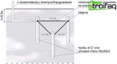
The ground loop is made using steel rods, driven into the depth, and strips connecting them
Ground loop device
Most often, grounding is performed using metal rods – electrodes buried in the ground and interconnected at the top by a strip or rod. This design is connected to the house guard with a cable or the same metal strip..
Moreover, the depth of the location of the electrodes depends on the saturation of the soil with water. The higher the groundwater, the less depth is required..
The distance from the house should be at least 1 m, but not more than 10 m.
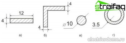
Minimum allowable dimensions of fittings used for the installation of grounding devices
The grounding contour of a private house is carried out using rods, which can be a steel corner, fittings with a smooth structure, a pipe, an I-beam. The cross-sectional area of the electrodes should be more than 1.5 cm2, and the shape should be convenient for driving into the ground.
The rods are arranged in a row or in the form of a geometric figure: triangle, square, rectangle. It depends on the ease of installation of the structure and the area that can be used. A contour equipment option around the perimeter of the building is also possible. But the most common is still the triangular ground loop. At the top of the figure, electrodes are driven in, which are interconnected by a steel strip.
Important! The ground loop must always be below the freezing ground.
In other words, grounding can be done using improvised material. But it is possible to purchase a ready-made kit for arranging the ground loop. It includes rods – copper-plated electrodes, 1 m long, connected by a threaded connection. Such kits are not cheap, but significantly simplify the task and are durable in use..
How to make a calculation
Of course, grounding can be done empirically. For example, to determine the depth of water, to retreat from the house to the optimum distance and to arrange a triangular contour. Weld the electrodes with each other and measure the resistance of the resulting structure. If it turns out to be too large, deepen still additional electrodes, attach them to the previous ones and take measurements again. And so, until the measurement result meets the requirements.
Experts strongly recommend that before making the ground loop, make all the necessary calculations. Determine the number of vertical grounding – electrodes, which will be needed, and the length of the connecting strip, depending on the resistance of the soil.
First you need to determine the resistance of one vertical ground electrode – electrode.

Formula 1. Resistance of one vertical ground electrode system
Where,
R0 is the resistance of one electrode, Ohm;
Req – equivalent ground resistivity, Ohm * m;
L is the length of the electrode, m;
d is the diameter of the electrode, mm;
T is the distance from the middle of the electrode to the surface of the earth, m.

Table 1. Soil resistivity

Table 2. The value of the seasonal climatic coefficient of soil resistance
The value of soil resistance can be taken from the table, but if the soil is heterogeneous, then

Formula 2. Equivalent resistivity of heterogeneous soil
Where,
Ψ – seasonal climatic coefficient;
P1, P2 – soil resistivity (1 – upper layer, 2 – lower layer), Ohm * m;
H– thickness of the upper soil layer, m;
t is the depth to which the electrode is clogged, m (trench depth);
If you do not take into account the resistance of the horizontal ground electrode, then the number of electrodes can be found by the formula:
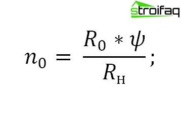
Formula 3. The number of electrodes excluding the resistance of the horizontal ground electrode
Where,
n0 is the number of electrodes;
Rн– normalized grounding resistance, based on PTEEP.

Table 3. The highest allowable resistance value of grounding devices (PTEEP)
We determine the current resistance of the horizontal ground electrode according to the formula:

Formula 4. The resistance of the spreading current of the horizontal ground electrode
Where,
Lg – the length of the ground electrode;
b– width of the ground electrode;
ψ – seasonality coefficient of the horizontal ground electrode;
ɳГ – demand coefficient of horizontal grounding conductors.
The length of the ground electrode is as follows:

Formula 5. The length of the horizontal ground electrode
Where,
a is the distance between the electrodes.
The resistance of the vertical electrodes, taking into account the horizontal ground electrode:

Formula 6. The resistance of the vertical ground electrodes – electrodes, taking into account the resistance of the horizontal ground electrode
The total number of vertical grounding electrodes is equal to:
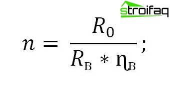
Formula 7. The final number of vertical earthing
Where,
ɳв – demand factor of vertical grounding conductors.
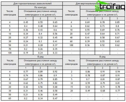
Table 4. The utilization of earthing
An indicator called “utilization factor” shows the effect of currents on each other, depending on the location of the vertical electrodes. If the electrodes are connected in parallel, then the currents flowing through them affect each other. The smaller the distance between the electrodes, the greater the overall resistance of the circuit..
If the number of grounding conductors obtained by the last formula is not integer, round it to the nearest integer.
Ground loop: circuit
After all the calculations are made, we choose a convenient place for the location of the ground loop. We determine which figure the electrodes will be located. Then we draw a ground loop diagram taking into account the type of materials used. Be sure to indicate what was used for the electrodes and for the connecting strip, their length and diameter, depth.
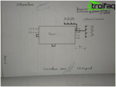
Ground loop: diagram on the passport (outside the building) – example
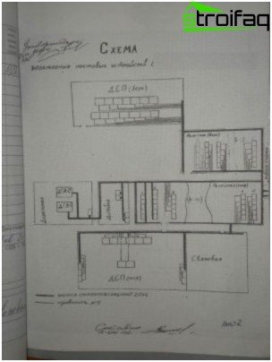
Ground loop: passport diagram (inside the building) – example
All this will be useful to us not only for ease of installation and for the future, but also in order to get a passport for the ground loop. When the installation work is completed and the resistance of the circuit is measured, energy managers who will need to be invited will issue and endorse all the necessary documentation for the ground loop. Of course, this is if everything is done correctly..
Ground loop construction
Installation of the ground loop is best started in the warm season. So it will be easier to carry out earthwork and measure grounding resistance. Then it will be more reliable to see at what depth groundwater lies.
Consider the option of arranging the ground loop in the form of a triangle:
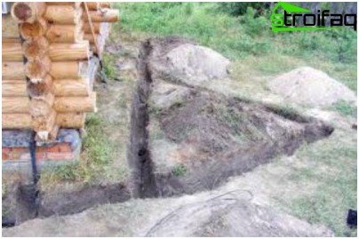
To equip the ground loop, it is necessary to dig a trench to the depth of freezing of the soil
- We have already chosen a place. Therefore, we dig a trench with a depth of 0.7 m to 1 m (below freezing), a width of 0.5 – 0.7 m. The lines should form a triangle with a side whose length was determined during the calculations.
- From one of the corners of the triangle we dig a trench towards the power shield.
- At the vertices of the triangle we drive in grounding electrodes. What exactly will we use for this, it is necessary to decide at the stage of calculations. Let as an example it be a steel angle of 50 * 50 mm. If the density of the soil does not allow you to simply clog the rods, you will have to drill wells.
- We deepen the rods so that they protrude above the ground. If we still had to drill wells, set corners in them and fill up with soil mixed with salt.
- We take a steel strip of 40 * 5 mm and weld to the electrodes, forming a contour in the form of a triangle. Then from one of them we lead a strip to the power cabinet.
- We fix the strip to the ground wire or power shield using a bolt with a diameter of 10 mm. In this case, the bolt must be welded to the strip.
- At this stage, we check the resistance of the ground loop with an ohmmeter. This device is not cheap, it makes no sense to buy it. It is better to invite employees from energy management to take measurements and fill out the passport of the ground loop. Resistance must be less than required. If not, then you need to drive extra electrodes.
- If the resistance turned out to be sufficient, we fill the trench with homogeneous soil without construction debris and rubble.
Important! During further operation in abnormally dry weather, it is advisable to water the ground loop from the hose to reduce its resistance.
All work related to the calculations and installation of the ground loop can be entrusted to professionals who have more experience. This will help save time and nerves. But if you are inclined to do everything with your own hands, go for it. Your creation will protect you and your family.


