Grounding systems
Grounding is one of the most important technological methods of protection against electric shock when working with electrical devices. For proper modernization or repair of wiring, you need to accurately understand which grounding system is used at the facility. Human safety and the normal operation of equipment depend on this. Information is also important when creating a reconstruction project. Accordingly, it is necessary to study all available grounding systems, differences from each other, as well as technology for their installation.
Content
- Classification of grounding systems
- TN system and its variants
- What is a TT system?
- IT system: features
- Grounding device technology
- Traditional technology and materials
- Modular grounding system progressive protective circuit
Classification of grounding systems
The International Electrotechnical Commission (IEC) and Gosstandart have installed types of grounding systems.
All of them are indicated in the PUE (Electrical Installation Rules). Distinguish:
- TN system (with TN-C subsystems, also TN-S and, finally, TN-C-S);
- TT system
- IT system.
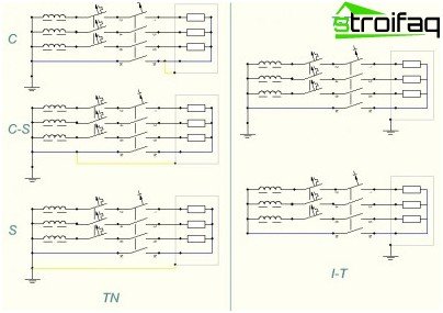
Grounding systems TN, TT, IT
They differ in the source of electricity and the method of grounding electrical equipment. The type of grounding system is indicated by the letters:
1. The first letter determines how the power source is grounded:
- if it is T – then there is a direct connection of the zero working conductor (neutral) of the electric power source to the ground;
- if it is I – then the neutral source of energy is connected to the earth exclusively through resistance.
2. The second letter defines the grounding in the conductive open parts of the electrical installation of the building:
- the letter T denotes local (separate) grounding of electrical equipment and a power source;
- the letter N indicates that the power source is grounded, but consumers are only grounded through the PEN conductor.
3. The following letters after N determine the functional way in which the zero working and zero protective conductors are arranged:
- if S stands, then the functions of the working (N) and protective (PE) conductors are provided with separate conductors;
- if C stands, then the functions of the zero working and protective conductors are provided by a common conductor (PEN).
TN system and its variants
The TN system is distinguished by the presence of a grounded neutral: open conductive parts of any electrical installation are connected to a specific grounded neutral point of the power supply by means of special zero protective conductors.
The term “dead grounded neutral” means that the neutral (zero) at the transformer substation is connected directly to the ground loop (i.e., grounded).
The main condition for electrical safety TN is as follows: the current value between the open conductive part and the phase conductor during a short circuit should exceed the value of the electric current of the protection device for a normalized time.
The popular TN-C subsystem
The TN-C subsystem is TN, in which the conductors (zero working as well as protective) are aligned throughout the system (into 1 PEN conductor), i.e. protective grounding is made. This is the most used variety of TN since Soviet times. However, this system is now outdated. Of modern electrical installations, it is found only in street lighting (in order to save, as well as reduced risk). For new housing, it can not be recommended. Now it has been replaced by more modern systems.
Grounding Option TN-S
The TN-S subsystem is TN, in which the conductors (zero working as well as protective) are separated throughout the system. It is a modern, most secure, but the most expensive system. It has long been used in telecommunication networks (which is noteworthy, when it is used, interference in a low-voltage network is excluded).
TN-C-S – device specifics
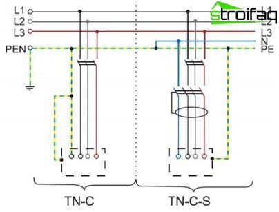
Grounding Systems TN-C, TN-C-S
Subsystem TN-C-S – can be attributed to the intermediate option. In it, the zero worker, as well as the protective conductors are combined only in one part of it. Usually – in the main shield of the building (where protective grounding is supplemented by protective grounding). Throughout the building, these conductors are further separated. The system is optimal from the perspective of price-quality ratio. This scheme is currently the main one, which can be implemented in separate parts of electrical installations during reconstruction. Other systems grounding systems do not allow this. Cross-sections of conductors are selected based on the values of currents (calculated) flowing through them. The cross-sectional area (minimum) of the PEN conductor is 4 mm2. It must be foreseen that the switchboard has separate terminals on the PEN bus (for each conductor – N and PE). When using a stranded or single wire as a PEN conductor, its insulation color should be exclusively yellow-green.
What is a TT system?
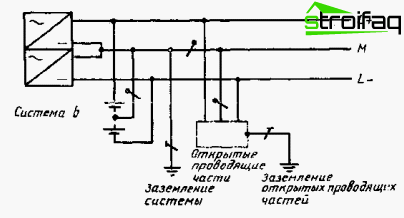
TT system
This system is characterized in that the source zero in it is grounded, while the open conductive parts of any electrical installation are connected to ground, which is electrically independent of the grounded zero (neutral) power source. In other words, the object applies ground loop, which has nothing to do with zero. Today, this system as the main one is used in mobile structures, for example, cabins, wagon-houses, etc. (where it is not always possible to mount an earthing switch in accordance with the required standards). It is noteworthy that the coordination of its application is more complicated than TN. The use of RCDs becomes mandatory, a good grounding is also necessary (namely 4 Ohms at 380 V), there are many features when selecting the necessary circuit breakers.
IT system: features
This system is characterized in that the zero source in it is isolated from the ground or grounded through devices that have high resistance, and the conductive open parts of electrical installations are grounded using grounding devices. IT is extremely rare. Basically – in the electrical installations of special purpose buildings. For example, for emergency lighting and power supply in hospitals. In general, where increased safety and reliability requirements are imposed.
Grounding device technology
There are several technologies for installing the ground loop. The most used two: the traditional and modular pin earthing system.
Traditional technology and materials
Grounding is carried out from ferrous metal: corners, pipe strips, etc. Installation begins with the creation of a project that reflects the place where the ground loop will be arranged, the location of technical communications in the ground. Then, focusing on the object, into the soil to a depth of 3 m, at a distance of about 5 m from another, metal products (electrodes) of a certain section (not < 3). After that, these electrodes are welded into a common circuit around the perimeter using a metal strip..
This technology has been core for many decades. However, it has a number of drawbacks (for example, metal corrosion, the complexity of the installation, etc.), so now they are trying to replace it with another, more modern and advanced grounding technology.
Modular Grounding System
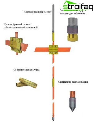
Modular earthing system
What is included?
- It consists of rods made of stainless steel and coated with copper. They are placed vertically in the ground. Each of these rods reaches a length of about one and a half meters, and in diameter – 14 mm, the mass of the 1st element – no more than 2 kg. On both sides of each rod, copper-plated threads are cut 30 mm in length.
- The steel elements of this system are interconnected using brass couplings..
- The modular grounding system kit also includes a brass clamp used to connect horizontal (special steel strips or copper wire passing from the distribution panel directly to the grounding circuit of this system) and vertical (copper-plated steel rods) grounding elements.
- Also included are two steel lugs that will be attached to the rod by screwing onto copper-plated threads. The tips will have to be selected depending on the soil (especially hard or ordinary). It will pass the entire device of this building grounding system.
- For anticorrosion protection of all grounding elements, a protective paste is usually applied, which processes the elements of the entire future grounding system.
- For a safer and more reliable connection of horizontal and vertical components use a protective tape (for example, PREMTAPE).
How is the installation?
Installation of a modular pin grounding system takes place in several stages:
- The first vertical steel pin is installed.
- Intermediate resistance measurement.
- The remaining vertical pins are mounted.
- Horizontal earthing switch.
- Then the elements are connected and processed with a protective tape.
Benefits of a modular pin earthing system
- Allows to save the area (can be arranged on 1 m2 of the area).
- Simple, does not require laborious earthworks.
- No welding required.
- You can use this grounding for any type of soil
- Great depth is reached – up to 50 m.
- Stainless steel conductors used.
- No special equipment needed.
- Long service life.
From the foregoing, we can conclude that today the most rational is the use of the TN-C-S system and the modular pin technology of its installation. All the facts indicate that the technologies of the grounding device of the latest generation in many ways surpass the traditional ones. Their use reduces the time of work, reduces financial costs, increases the service life of grounding elements.


