Grounding and grounding of electrical installations
Our whole life is inseparable from all kinds of electrical appliances. The failure of any electrical equipment is a frequent and completely normal phenomenon, not a single device can work forever and without a single malfunction. Our task is to protect these electrical assistants from short circuits or overloads arising in the circuit, and ourselves from damage to the body by high voltage. In the first case, all kinds of protective devices come to the rescue, but grounding and grounding of electrical installations are used to protect a person. This is one of the most difficult parts of electrics, but we will try to figure out what is the difference between these works, and in what cases it is necessary to apply certain protective measures.
Content
- Electrical shock protection
- What is grounding?
- Classification of grounding systems
- Deprecated TN-C System
- For the modernization of old houses TN-C-S
- TN-S System Specifics
- TT system features
- Characteristic differences of the IT system
- What is grounding
- Grounding and grounding: what is the difference?
- Grounding (Grounding) Requirements
- What and when to ground
Electrical shock protection
If automatic devices, plugs and other protective devices do not respond to a malfunction, and as a result a breakdown of the internal insulation is formed, an increased voltage appears on the metal casing of the installation. Touching such a device by a person can lead to muscle paralysis (with a current strength of 20-25 mA), which prevents independent separation from contact, arrhythmias, disturbances in blood flow (at 50-100 mA), and even death.
If parts of the electrical installation due to technical features must be energized, then they must be enclosed in accordance with generally accepted safety precautions, for example, special covers, barriers or mesh barriers. In order to prevent accidental electric shock when the insulation layers are damaged, protective grounding and grounding are used. To understand how grounding differs from grounding, you need to know what they are.
What is grounding?
Often, beginning electricians do not quite understand what is the difference between grounding and grounding. Grounding is the connection of an electrical installation to earth in order to reduce touch voltage to a minimum. It applies only to networks with isolated neutral. As a result of the installation of grounding equipment, most of the current flowing to the housing must go along the grounding part, the resistance of which should be less than the rest of the circuit.
But this is not the only grounding function. Protective grounding of electrical installations also contributes to an increase in emergency fault current, no matter how contrary to its purpose. When using an earthing switch with a high resistance value, the fault current may be too small for the protective devices to operate, and the installation will remain energized in an emergency, posing a huge danger to humans and animals.
An earthing switch with conductors forms a grounding device, where, in fact, it is a conductor (a group of conductors) connecting the conductive parts of the units to the ground. By purpose, these devices are divided into the following groups:
- lightning protection, for the removal of a pulsed lightning current. They are used for grounding lightning rods and arresters;
- workers, to maintain the required operating mode of electrical installations, both in normal and emergency situations;
- protective, to prevent damage to living organisms by electric current arising from the breakdown of a phase wire on the metal case of the device.
All grounding conductors are divided into natural and artificial.
- Natural – these are pipelines, metal structures of reinforced concrete structures, casing pipes and others.
- Artificial grounding conductors are structures built specifically for this purpose, that is, steel rods and strips, corner steel, substandard pipes and more.
Important: for use as natural grounding, pipelines of flammable liquids and gases, pipes coated with anti-corrosion insulation, aluminum conductors and cable sheaths are not suitable. It is strictly forbidden to use water and heating pipes as grounding conductors in residential premises.
Classification of grounding systems
Depending on the connection scheme and the number of zero protective and working conductors, the following grounding systems for electrical installations can be distinguished:
- TN-C;
- TN-C-S;
- TT
- IT.
The first letter in the name of the system indicates the type of grounding of the power source:
- I – live parts are completely isolated from the ground;
- T – the neutral of the power source is connected to the ground.
By the second letter, you can determine how the open conductive parts of the electrical installation are grounded:
- N – direct connection with the ground point of the power source;
- T – direct connection to the ground.
The letters immediately after N, through a hyphen, indicate a way to create a protective PE and working N neutral conductors:
- C – the functions of the conductors are provided by one PEN conductor;
- S – the functions of the conductors are provided by different conductors.
Deprecated TN-C System
Such grounding of electrical installations is used in three-phase four-wire and single-phase two-wire networks, which prevail in old-style buildings. Unfortunately, this system, despite its simplicity and accessibility, does not allow to achieve a high level of electrical safety and is not used on newly constructed buildings..
For the modernization of old houses TN-C-S
Protective grounding of electrical installations of this type is mainly used in reconstructed networks, where the working and protective conductors are combined in the input device of the circuit. In other words, this system is used if it is planned to locate computer equipment or other telecommunications in an old building where TN-C type grounding is used, that is, to make the transition to the TN-S system. This relatively inexpensive circuit offers a high level of security..

TN-C-S System Migrates From Legacy TN-C To TN-S
TN-S System Specifics
Such a system is distinguished by the location of the zero and working conductors. Here they are laid separately, and the neutral protective conductor PE connects immediately all the conductive parts of the electrical installation. To avoid re-grounding, it is enough to arrange a transformer substation having a basic grounding. In addition, such a substation allows to achieve a minimum conductor length from the cable entry into the electrical installation to the grounding device.

TN-S system: 1. Earthing switch; 2. Conductive parts of the installation.
TT system features
The system, where all current-carrying open parts are directly connected to the ground, and the earthing switches of the electrical installation do not have an electrical dependence on the earthing switch of the substation neutral, is called TT.

The TT grounding system is characterized by the presence of grounding conductors for each conductive part of the installation
Characteristic differences of the IT system
The difference between this system is the isolation of the neutral source of the power supply from the ground or its grounding through devices with high resistance. This method allows you to minimize the leakage current to the casing or to the ground, so it is better to use it in buildings where stringent electrical safety requirements are set..

IT system: 1. Ground resistance of the power supply neutral. 2. Earthing switch. 3. Open conductive parts. 4. Grounding device.
What is grounding
Zeroing is the connection of metal parts that are not energized, either to the grounded neutral of the lowering three-phase current source, or to the grounded terminal of the single-phase current generator. It is used to ensure that when an insulation breakdown and current gets on any non-conductive part of the device, a short circuit occurs, which leads to a quick trip of the circuit breaker, blowing of fuses or the reaction of other protection systems. It is mainly used in electrical installations with earthed neutral.

Schematic diagram of the zeroing of electrical installations
An additional installation of the RCD in the line will lead to its operation as a result of the difference in the current strengths in the phase and zero working wires. If both an RCD and a circuit breaker are installed, then a breakdown will lead to the operation of either both devices, or to the inclusion of a faster element.
Important: When installing the grounding, it must be taken into account that the short-circuit current must necessarily reach the melting value of the fuse insert or the circuit breaker, otherwise the free flow of the short-circuit current through the circuit will lead to voltage on all zeroed housings, and not just on the damaged section. Moreover, the value of this voltage will be equal to the product of the resistance of the zero conductor by the fault current, which means it is extremely dangerous for human life.
The serviceability of the neutral wire must be monitored very carefully. Its break leads to the appearance of voltage on all zeroed buildings, since they automatically turn out to be connected to the phase. That is why it is strictly forbidden to install in the neutral wire any protective equipment (circuit breakers or fuses) that form its gap when triggered.
In order to reduce the likelihood of electric shock when the neutral wire is broken, re-grounding is carried out every 200 m of the line. The same measures are taken at end and inlet supports. The resistance of each re-earthing switch should not exceed 30 Ohms, and the total resistance of all such grounding wires should not exceed 10 Ohms..
Grounding and grounding: what is the difference?
The main difference between grounding and grounding is that when grounding, safety is ensured by a rapid decrease in voltage, and when grounding, by disconnecting a portion of the circuit in which a breakdown of current to the housing or any other part of the electrical installation occurs, while in the period between the short circuit and the termination power supply, there is a decrease in the potential of the electrical installation enclosure, otherwise an electric current discharge will pass through the human body.
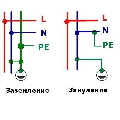
Grounding and grounding circuitry
Grounding (Grounding) Requirements
In all electrical installations where the neutral is isolated, protective earthing is necessarily carried out, and it should also be possible to quickly search for earth faults.
If the device has a grounded neutral, and its voltage is less than 1000 V, then only grounding can be used. When equipping such an electrical installation with a separating transformer, the secondary voltage must be no more than 380 V, lowering – no more than 42 V. At the same time, only one power receiver with a rated current of the protective device of no more than 15 A is allowed to be supplied from the separating transformer. In this case, grounding or grounding is prohibited secondary winding.
If the neutral of a three-phase network up to 1000 V is isolated, then such electrical installations must be protected against breakdown as a result of damage to the insulation between the transformer windings and the breakdown fuse, which is mounted in the neutral or phase from the low voltage side.
What and when to ground
Protective grounding and grounding of electrical installations must be carried out in the following cases:
- With alternating rated voltage over 42 V and constant rated over 110 V especially hazardous and outdoor installations.
- With alternating voltage over 380 V and constant over 440 V in any electrical installations.
Grounds of electrical installations, apparatus drives, frames and metal structures of switchboards and panels, secondary windings of transformers, metal sheaths of cables and wires, cable structures, busbars, ducts, cables are grounded, steel pipe wiring and electrical equipment located on moving parts of mechanisms.
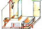
In residential and public buildings, electrical appliances with a capacity of over 1300 watts are necessarily subject to grounding (grounding). If suspended ceilings are made of metal, then it is necessary to ground all metal cases of lighting fixtures. Bathtubs and shower trays made of metal should be connected to water pipes by metal conductors. This is done to equalize electrical potentials. To ground the cases of air conditioners, electric stoves and other electrical appliances whose power exceeds 1300 W, a separate conductor is used, connected to the neutral conductor of the power supply. Its cross section and the cross section of the phase wire laid from the switchboard must be equal.
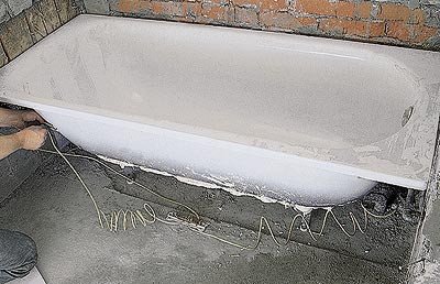
To equalize the electric potentials, the bath must be closed to water pipes
A complete list of equipment requiring grounding or grounding, as well as devices where, on the contrary, it is allowed to neglect these protective measures, can be found in the Electrical Installation Code (Electrical Installation Rules). Here you can find all the basic rules for grounding electrical installations.
The grounding and grounding device is a very responsible job. The slightest error in the calculations or neglect of one seemingly insignificant requirement can lead to a great tragedy. Only people with the necessary knowledge and experience are required to carry out grounding.